<-CLICK HERE FOR SCOOBY TECH. POSTS ONLY! CLICK HERE FOR GRAN TURISMO POSTS ONLY!->
1998 Impreza Turbo Project Car + Expanding WRX Knowledge Base!
Showing posts with label AUDIO. Show all posts

Sunday, 2 January 2011

Relocating the Stock-Aerial Part 1

I know Scooby's aren't designed with aesthetic perfection in mind, but its a shame they follow the utilitarian Japanese convention of bolting a tacky plastic thing on afterwards with an 80's pull-out style aerial in, usually on the driver's A-pillar. Even the 60-reg Toyota Hilux coming in at work, which are pricey trucks, still have these things and, while I'm sure they function superbly, they don't half look crap.

I've been planning to re-locate the aerial onto the roof of the Scoob for a while now and change it from a tacky telescopic metal one to a BMW-style 'shark-fin', but you could fit a rally-style mast-aerial, a bee-sting or a GPS-box lookalike in the same way. Its not a difficult job at all, but a brave enough one for me to struggle to get round to it. Doesn't look like it'll be any time soon, with all the other jobs mounting up [
power-steering is gonna need looking at first I think], but I reckon its a sound idea so I'll write it up anyway.

Removing the Stock Aerial:

Unclip and remove the plastic cover on the driver's A-pillar inside the car and cut the wires going to the aerial-mount.

Remove the two screws holding the aerial-mount with a flat-head screwdriver and prize the plastic-mount away from the a-pillar.

Bridge the holes in the a-pillar with metal-filler, or just stick about 5 layers of black-tape over the back of them, then fill the outer layer with P38 body-filler. Its only a tiny area so shouldn't be hard to sand, prime and paint-match.

Installing the New Aerial:

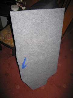
Inside the car, unclip and pull down the roof-lining. I'm still unclear on how to do this so, for now, refer to the Body section of the workshop manual here - http://www.scoobylab.co.cc/2010/12/manuals.html.

Find a suitable spot and drill a hole wide enough for the new-aerial's mounting-stud. Drill from the outside in and it's easy to dent the roof so drill slowly, use plenty of oil on the bit and it might be worth starting with a small pilot-hole to make sure the location is accurate.

Place the mounting-stud of the new-aerial through the hole and stick the base down onto the roof. Tighten the nut onto the mounting-stud inside the car.

Extend the cut-off wires at the a-pillar, if necessary, across the inside of the roof to meet the cable on the new-aerial and tape it into place. It's likely the new unit will have a male FM-aerial connector on it [same as the one in the dash that plugs in to the head-unit], so you could cut it off and hard-wire it, but for a nicer job I'd recommend getting a female FM-aerial socket from Halford's for a couple of quid and crimping it to the a-pillar wire. That way the aerial can be un-plugged easily if some idiot decides to nick your new bee-sting and you have to a quick replacement.

Clip the roof-lining back up into place and replace the plastic-cover to the inside of the a-pillar.

Saturday, 16 October 2010

Fixing the Subwoofers

FINALLY! After four months I've discovered what was making my subs work so strangely! This is definitely worth noting as it is likely a very common problem and could stop you needing to replace your subs/amp if you have the same symptoms.

FAULT FINDING:
I took the system out of the boot while fitting the coilovers and when I put them back in they were almost inaudible. Everything appeared to be working so I fiddled with the settings on the head-unit for a few days, but they were so quiet I didn't even notice the fuse had blown at some point. I replaced it, but they kept on blowing after a few days so I checked all the wiring for splits where the metal could be touching the car somewhere. They were all fine.I thought itcould be an earth problem, but if the black cable isn't grounded properly then the amp wouldn't turn on at all. I then checked and re-checked the remote cable from the head-unit to the amp, as this was a horrible problem I had with the system in my Escort, but it all just looked hunky dory. The speakers were moving too, wildly back and forth from one extreme to another, so they were definitely getting a signal.

As for the sound, most of my passengers were convinced I was losing my mind, as the Infinity Kappa's in the doors are pretty bass heavy as is, and kept telling me nothing was wrong. After a couple of busy months though, lugging round a small person's weight of subs and replacing fuses every 5 minutes, I just had to get to the bottom of the quiet running or get rid of the install altogether.

I'd checked and re-checked everything, so the problem had to be inside the components themselves. If a circuit had gone somewhere in the amp then I'd have to buy a new one, but luckily [i guess] the problem was inside the sub box. I guess it must have been stored somewhere damp before I bought it, plus the Scoob's boot and my porch probably weren't much better, because the wiring on the back of the speaker-terminals had started to really corrode in some way. I don't know if you can quite see in the photo, but it's a white powdery crud that covered the brass terminals and was starting to move up the copper cable inside the plastic sheath. I only know of aluminium corroding in this way, never copper, brass or gold-plated bits, so I suppose it might have been some alloy in the solder[?] It was the joins that held the worst of it and when I was checking one wire the crumbly solder broke straight off. Idon't know how the difference between these corroded wires working and breaking was sosudden, because it looks like they've been rotting for a while, but at least it's an easy fix and peace of mind at last!


FIX:
I cut the cables off a good cm past the end of the corrosion, stripped the ends and, instead of soldering them back on, I crimped on some new gold-plated spade-sockets, £3.99 at Halfords, but at least I know this won't happen again. I then took the brass spade-connectors off the terminal, burned the solder off them on the cooker and gave them a good rub with emery, before wiping any trace of the corrosion off everything. I hooked up the new spades and wrapped them in a nice piece of heat-shrink. As soon as I turned the head-unit on the bass was back! YES!

Friday, 14 May 2010

Carpeting the Boot Install

Got round to carpeting the plywood install in the boot at last with some nice grey acoustic cloth, filched from the skip at work.

I just placed each plywood section onto a piece of the cloth, folded about 3 inches round the back and tacked it down every 4 or so inches along. For the curves and fiddly bits I cut the fabric edge into strips at the corner apexes and at points along the curves, which may not be the professional way, but certainly recreates the shape of the wood well and looks great!

I would recommend sticking the carpet down with spray-glue before tacking the backside, but I didn't bother. As the plywood is so thin, nails and carpet-tacks we're no good, so I used drawing pins, which are the perfect length. This also keeps things cheap and incurs the first cost of the entire install @ £1 for 3 boxes :) - quite amateur looking though, at least they're hidden away.


This has really made the boot look complete and useable! Just a few more finishing touches - a storage area on the right hand side and neatening up the jack compartment on the left side - and it's done.

NB: I have now weighed each part of the install, including the amp and sub-box, and the total comes to 32kg - about 5 stone! - in other words the weight of a small passenger...

Monday, 26 April 2010

Quick + Dirty Boot Install...

Decided to make a neat but cheap install to hold my heavy subs in place without having to screw through the under-tray. Having already bought the electricals, this tidy install didn't cost me a penny to make...


I got hold of a large sheet of thin plywood being thrown out at work, laid the Subaru boot-mat over the plywood and drew round the mat to make a template. I then cut the shape of the boot-mat out with a jigsaw.

This won't fit into the boot in one piece, so I cut across the wooden floor left to right just before the point where the floor starts to widen out. The back-piece now forms a fixed base for the subs to sit on, where the front-piece can be still be lifted out to access the spare wheel. The subs can only go back a certain amount before the width of the twin-box hits the corners of the rigid section under the parcel shelf, so I measured the optimum depth of the back-piece while still allowing enough room up front to life the spare wheel out. The subs are still proud of the back-piece by about half a cm, but this makes a nice lip for the front-piece to slide under.

I cut a section from the left side of the front-piece about three-quarters of the way along to become a base for the amp to sit on, which is also fixed in place. The entire right side of the front-piece lifts out and I drilled two holes and inserted a blue cord to make a handle to lift it, which was an old lanyard-cord, also scavenged from the skip at work.


I screwed some 2cm x 4cm strips of boxwood along the underside of the back-piece, (which were, along with the screws again filched from the skip at work) and two long strips at the left side that continue forward to the back of the boot for the amp-piece to screw onto. I finally put two strips on the right front-piece, one either side of the spare-wheel well so the different floor heights match up. This meant I could drill holes for all my wiring and hide it away underneath the wooden boot-floor, as shown in the pics below, a really neat touch.


So there you go, reasonable install at nil cost.. and no more sliding sub-box! I have now also got hold of a roll of some very nice light-grey acoustic carpet from, yes you guessed it, the skip at work hehe, so I'l be covering up the cheap plywood look as the summer gets going.
 
ScoobyLab + Propjam 2010/11